 EIDE Drives
All Caviar drives have a jumper block (J8) located between the 40-pin
IDE connector and the power connector. These jumpers select the physical
detection options on the hard drive. All Caviar drives are factory set
for Cable Select installation.
Single-Drive Installation
If you are installing the drive as the only IDE drive on the cable
and the system plus the ribbon cable do not support Cable Select, place
the jumper shunt in the neutral storage position.
Dual-Drive Installation
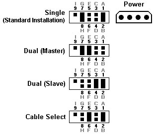
In dual drive installations (2 devices on the IDE cable), jumper shunts
are needed to designate which device is master (first device detected)
and which is slave (second device detected). Refer to Figure 1 or Figure
2 for an illustration of all jumper settings.
If you have a dual installation, you must designate one of the drives
as the master and the other as the slave. The jumper pins on block J8
need to be configured for dual installation. If the other IDE device
on the cable is not a Western Digital IDE drive, consult its installation
guide for master/slave configuration.
To install a jumper shunt on the J8 jumper pins:
- Refer to Figures 1 or 2 to determine your configuration.
- Carefully place the shunt over the pins specified in the figure.
- Push the shunt into place until it is flush against the base of
the jumper block.
Note: Designation of a drive as either master or slave is generally
determined by jumper configuration, not by the order in which it is
daisy-chained to the other drive. The only exception is if the drive
is jumpered "cable select", and both the system and ribbon cable support
cable select.In this case, master and slave is determined by the position
on the data ribbon cable. Depending how the system controls the cable
select line on the ribbon cable determines where the master and slave
need to be attached. Refer to your system manual for more information.
Figure 1. (6 & 10
pin drives)

Figure 2. (9 pin
drives)
The pins on the drive may be designated by either letters or numbers.
EIDE Drives Greater than 2.1 GB
This section pertains to the Western Digital drives such as
AC32500 - The cylinder count of this drive is greater than 4095.
AC313000 - The cylinder count of this drive is greater than 16383.
The 16383 cylinder limit affects any drive larger than 8.4GB. There
is an additional BIOS limit of 32 GB. You may notice that a drive much
larger than 8.4 GB, such as WD400BB, has the same cylinder count. This
is because newer systems use INT13 extensions and no longer use the
cylinder count to recognize the drive痴 full capacity. However the symptoms
and the solutions are identical. For more information on these limitations,
please read this.
Some system BIOS's CANNOT properly recognize hard drives that have
more than 4095 cylinders, while others CANNOT properly recognize
hard drives that have more than 16383 cylinders at the 8.4 and 32 GB
capacity limits. You will know if your system BIOS has this limitation
after installing your drive. On the initial boot your system may a)
lock up, or b) show a much smaller drive capacity.
a) If your system locks up (i.e. does not respond after a few minutes),
follow these steps:
- Turn your system power off.Check the IDE interface and power supply
cables to make sure that they are properly connected.
- Check jumper settings.
- Turn your system power on.
- Try to enter your CMOS setup.
If your system still doesn't respond, it may be because you have a
system BIOS that doesn't support drives with more than 4095 or 16383
cylinders (depending on the size of the drive and the age of the system).
If this is the case, these solutions are available:
- Use Data Lifguard Tools EZ-Install. If your system locks up before
you can enter CMOS, you may need to turn your system power off and
disconnect the IDE cable from the system to access your CMOS setup.
- Enter your CMOS setup. Refer to your system manual for instructions.
- Select the Hard Disk Type option for the new Western Digital
hard drive. Select a User Defined drive type and enter:
1023 x 16 x 63.
- Turn your system off and reconnect your IDE cable to the system.
These new settings will allow your system to boot so that you
can install Data Lifguard Tools EZ-Install to access the full
capacity of your drive.
- OR -
If you don't have the User Defined drive type, use option 2 or
3 below.
- If you have a 6 or 10-pin drive, re-jumper the drive using the alternate
jumper settings as shown in figure 3 and install Data Lifguard Tools
EZ-Install. This option changes the parameters reported to the BIOS.
If later on you move this drive to another system, you must put the
jumper back to the standard position.
Note: These alternate jumper settings WILL NOT work
for Windows NT, OS/2 Warp, Novell NetWare, or UNIX.
If you have a 9-pin drive, alternate
jumper settings can be used, however, this can cause problems. Therefore,
we do not recommend using the alternate jumpers on 9-pin drives.
- OR -
- Upgrade your BIOS. A properly upgraded BIOS will support the drive.
Contact your system manufacturer. See the list of common system and
BIOS manufacturers and their phone numbers.
Figure 3. Alternate Jumper Settings (6 &
10 pin drives)
Drive Rails
Some computer systems have 5.25-inch drive bays that require unique
sliding drive rails to complete the hard drive installation. Each
system manufacturer has a different type of drive rail and for this
reason, rails are not included with Western Digital hard drives.
If your system requires drive rails, you must contact the computer
system manufacturer directly to obtain the rails for your particular
system. The following is a list of the most common system manufacturers
and their corresponding phone numbers:
 WDC ATAの詳細情報